
The indicators are classified as “Pressure accessories” in the sense of the PED Directive 2014/68/EU, Article 2, paragraph 5 and are subject to Article 4, paragraph 1, letter (c), of the same Directive.
All the products range is suitable for use with fluids proper to the Group 1 and 2, as defined in Article 13, paragraph 1, letter (a) and letter (b), of PED Directive 2014/68/EU with reference to Regulation (EC) n.1272/2008, in accordance with safety classification A1, A2L and A3 in Annex E of standard EN 378-1:2016. Examples of A1 and A2L refrigerant fluids are:
– HFC R32, R134a, R404A, R407C, R410A, R507;
– HFO R1234yf, R1234ze and blends HFC/HFO R448A, R449A, R450A, R452A, R452B, R445A, R454B, R454C, R513A.
Examples of A3 refrigerant fluids are (HC hydrocarbon):
– R290, R600, R600a, R1270;
Saddle type indicators are excluded from the scope of Directive 2014/68/EU as piping components.
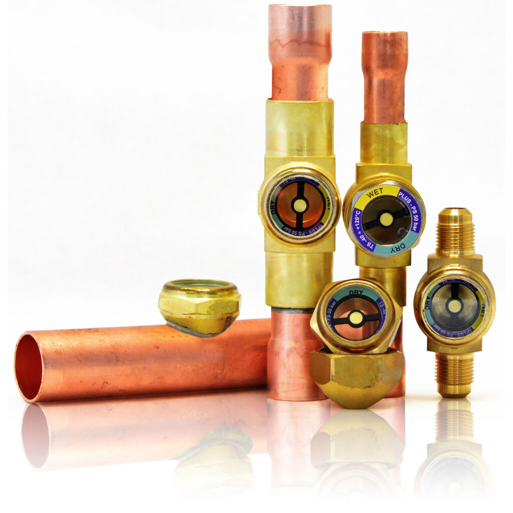
The function of liquid and moisture indicators is to check in real time the situation of flow in the system and the presence of moisture.
The indicators are made by embedding a spyglass directly into the body of hot forged brass EN 12420 – CW617N or in the annular indicator body of brass EN 12164 – CW614N. This forms a unique compact structure that minimizes the junctions between components, followed by removing possible leakage of refrigerant. To obtain a perfect sealing of glass in all indicators is used a modified Teflon gasket; in saddle type indicators the seal between the annular indicator and the body is done by an O-ring made of HNBR. In some models, the solder connections are made of copper EN 12735-1 – Cu-DHP. This indicators series is characterized by an element sensitive to moisture which changes colour from green to yellow depending on the concentration of moisture in the system. This indicators series allows also to check if the fluid passes in the indicator in the completely liquid state in charging conditions or in normal system operation: the presence of bubbles indicates the partial evaporation of the fluid along the liquid line.
During the first start, the colour of the element sensitive to moisture can be yellow, not only because of atmospheric moisture with which the indicator has come into contact but also for the presence of moisture in the circuit. When the moisture content of the refrigerant is normalized through the dehydrator filter, the colour of the element becomes green. The brazing of the indicators to the system shall be done with a low melting point alloy. During this process do not point the flame directly towards the body keeping it cooled in order to avoid compromising the seal of the gaskets.
NOTE: Where it is necessary to tighten the ring nut (equipped with a seal) to the body indicator, use the torque specified in the instructions provided with the product in order to ensure a perfect seal and resistance to PS maximum allowable declared.