PED Directive 2014/68/EU requires that: “Where, under reasonably foreseeable conditions, the allowable limits could be exceeded, the pressure equipment must be equipped with, or provision to be equipped with suitable protective devices, […]”. The mentioned device could be for example a safety valve; Its function is to prevent pressure from exceeding permanently the max allowable pressure PS of the equipment that protects. In any case, a short pressure peak limited to 10% of admissible maximum pressure is permitted. Some protection devices to be adopted in refrigerating systems and their features are indicated in EN 378-2 Standard “Refrigerating systems and heat pumps – safety and environmental requirements – Part 2: Design, construction, testing, marking and documentation”, harmonized with 2014/68/EU. EN 13136 Standard “Refrigerating systems and heat pumps – Pressure relief devices and their associated piping – Methods for calculation”, harmonized 2014/68/EU, highlights the possible causes of overpressure in a system; this Standard and EN ISO 4126-1 Standard “Safety devices for the protection against excessive pressure – Part 1: Safety valves, make available to users the principles of calculation and sizing for pressure relief device, including the safety valves.
COMPATIBLE FLUIDS: The safety valves are suitable for fluids such as air, nitrogen and refrigerants, in the physical state of vapour or gas, proper to Group 1 and 2, as defined in Article 13, paragraph 1, letter (a) and letter (b), of PED Directive 2014/68/EU with reference to the Regulation (EC) n. 1272/2008, according to safety classification A1, A2L in Annex E of the standard EN 378-1:2016. Examples of refrigerants fluids are:
– HFC R32, R134a, R404A, R407C, R410A, R507;
– HFO R1234yf, R1234ze and blends HFC/HFO R448A, R449A, R450A, R452A, R452B, R445A, R454B, R454C, R513A.
It is also possible to use these safety valves with HC hydrocarbon refrigerants such as:
– R290, R600, R600a, R1270;
proper to Group 1, as defined by Article 13, paragraph 1, letter (a) of PED Directive 2014/68/EU, with reference to Regulation (EC) n. 1272/2008 and according to safety classification A3, in Annex E of the EN 378- 1:2016 standard. The safety valve is not suitable for liquid; with equipment containing liquids plus vapour, it must be connected to vapour space and as far as possible from the liquid surface.
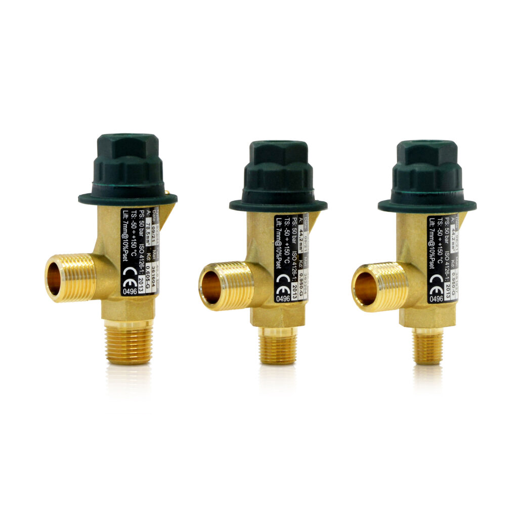
BODY: squared, hot forged brass EN 12420 – CW617N followed by machining (standard material adapted with directive 2014/68/EU).
OBTURATOR: obtained by machining bars of brass UNI EN 12164 – CW614N, (standard of material as directive 2014/68/EU); the obturator seat gasket is made of PTFE (Polytetrafluorethylene).
SPRING: Compression cylindrical helical spring made of round wire; the material is in accordance with UNI EN 10270-1 and the design is in accordance with UNI EN 13906-1. The spring always ensures the reclosing when the plant will restore the normal operating condition. The obturator is equipped with a mechanical lock, in this mode the spring movement does not exceed 85% of the total course and ensure enough space for discharge.
Safety valves shall be installed near an area of the plant where vapours and gases are present and there is no fluid turbulence; the position shall be as vertical as possible, with the cap vertically facing up. The coupling, if any, between the valve and the equipment to be protected shall be as short as possible; furthermore, it shall not have a passage section inferior to the valve inlet section. In any case, the pressure drop, at complete discharge capacity, shall be less than 3% of the pressure Po (= actual relieving pressure see par. 7.4 EN 13136 Standard). In selecting safety valve location and direction, it shall be taken into account, if not properly channeled, that discharge of refrigerant fluid under pressure, sometimes even at high temperatures, not to cause harm to people around it, especially in case of installation in enclosed rooms. A pipeline to convey discharged refrigerant outside of the room; the dimensions and geometry of pipeline shall not be such as to compromise valve operation: it shall not generate, at complete discharge capacity, a back pressure exceeding by 10% the pressure Po. It is advisable to check these conditions. When the installation of a conveying pipeline is not possible, it’s a good practice to provide adequate ventilation in the room and indicate, by means of special signals, the presence of discharged refrigerant. Furthermore, make sure that the safety valve shall not blow toward electric panels or equipment.