
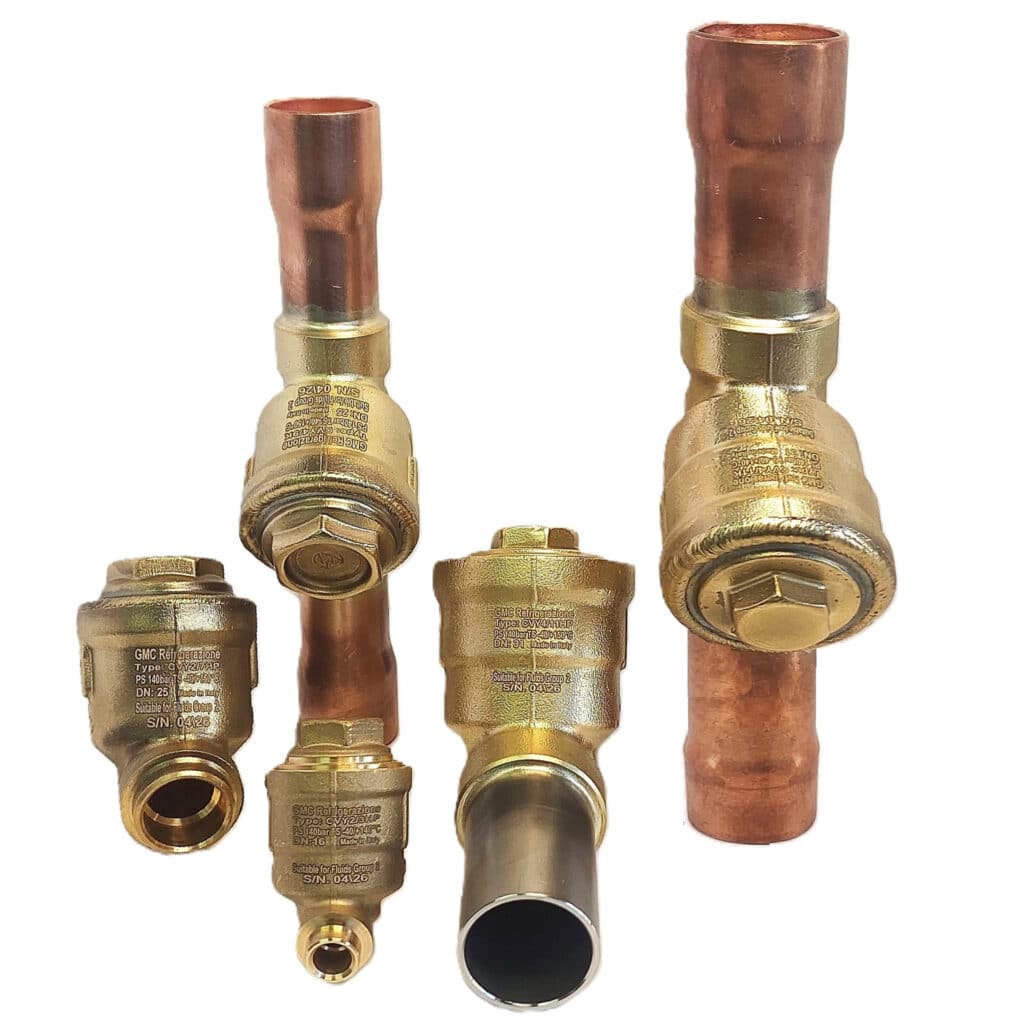
The Y check valves are considered “Pressure Accessories” as defined in Article 2, paragraph 5, of Directive PED 2014/68/EU. The whole series has been designed for the use of refrigerant R744 (CO2), classified by Article 13, paragraph 1, letter (b), of Directive PED 2014/68/EU as belonging to Group 2, or non-toxic fluid, non-flammable and non-explosive and listed in Appendix E to EN 378-1 as belonging to Group A1.
In the case of the Y check valves, the internal Nominal Dimensions (DN), foreseen now, vary from diameters of 16 mm for the smallest, up to diameters of 31 mm for the largest versions, while the maximum operating pressure, indicated in the reference tables do not exceed 140 bars for all models. According to Table 7 of Annex II of Directive 2014/68/ EU, all these products now fall under the scope of Article 4.3.
-Check Valve (CVY) are characterized by a mobile obturator that guarantees the unidirectional passage of the flow and have the peculiar characteristic of being able to be installed, with the longitudinal axis placed both horizontally and vertically, provided that the cap is always facing upwards; see the section “Installation” for further details.
In all series of Y check valves, the body and the cap are made of forged brass UNI EN12420 – CW617N. In the series CVY2.. HP connection pockets are made directly into the body and can accommodate, depending on the model, both metric tubes, typically stainless steel, and inch tubes, typically CuFe2P.
In the CVY4 series the connections of the HP line are made of stainless-steel tubes, while for the K line they are made of copper CuFe2P alloy. The obturator seal is made of modified PTFE and combines strength with excellent resistance to high temperatures; the spring that presses on the obturator is austenitic stainless steel AISI 302 designed specifically for the lifts required. The seal between body and cap, in the CVY2 series is entrusted to an EPDM O-ring, while in the CVY4 series, body and cap are sealed by tig welding.
The check valves of this series can be installed, with the longitudinal axis arranged both horizontally and vertically, provided that the cap is always pointing upwards: in this way the balance equation of the forces acting on the obturator and consequently the expected mOPD are best satisfied – therefore, carefully observe the installation instructions on the instruction sheet attached to the product or downloadable from the site. It is also necessary to provide in the installation of the CVY2 that there is enough space to unscrew and completely remove the plug and obturator before welding to the plant. Where there is vibration, appropriate damping and fixing systems should be provided to avoid overloading welds/brazes and connections.