
The check valves are classified as “Pressure accessories” in the sense of the PED Directive 2014/68/EU, Article 2, paragraph 5 and are subject to Article 4, paragraph 1, letter (c), of the same Directive.
All the products range is suitable for use with fluids proper to the Group 1 and 2, as defined in Article 13, paragraph 1, letter (a) and letter (b), of PED Directive 2014/68/EU with reference to Regulation (EC) n.1272/2008, in accordance with safety classification A1, A2L and A3 in Annex E of standard EN 378-1:2016. Examples of A1 and A2L refrigerant fluids are:
– HFC R32, R134a, R404A, R407C, R410A, R507;
– HFO R1234yf, R1234ze and blends HFC/HFO R448A, R449A, R450A, R452A, R452B, R445A, R454B, R454C, R513A.
Examples of A3 refrigerant fluids are (HC hydrocarbon):
– R290, R600, R600a, R1270;
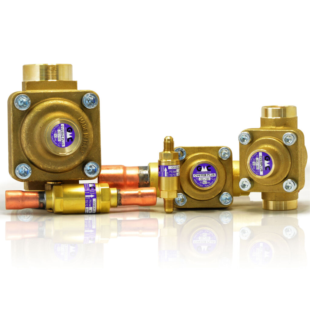
The function of the check valves is to ensure the unidirectional passage of the fluid through the pipes.
While installing the valve, make sure the arrow direction matches the direction of flow. We recommend installing the valves CV1 and CV3 Series with the vertical axis and the arrow pointing upwards; installations with the inclined or horizontal longitudinal axis are tolerable. The installation of the valves CV2 and CV4 series shall be done with the longitudinal axis lying in a horizontal plane and with the cover facing upward, furthermore only for this series is necessary to dismantle all the removable components from the valve and if the gasket does not remain on the cover, remove it manually from the body. The brazing of the valves with solder connections shall be done with a low melting point alloy. During this process do not point the flame directly towards the body and allow the latter to cool by natural convection in the air.